Alkaline electrolysers
Published on 6 January 2022
Alkaline electrolysers (AEL) are the oldest type of electrolyser and the closest to the classical explanatory electrolyser used in chemistry lessons to produce hydrogen and oxygen by splitting water molecules. They have 2 metal electrodes dipped into a water-based liquid and separated by a diaphragm porous to negative charged ions. Applying a current between electrodes releases hydrogen at the cathode and oxygen at the anode in the form of bubbles.
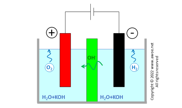
Schematics of an original alkaline electrolyser
With more than 200 years of development, alkaline electrolysis is the most mature, safest, most reliable and most enduring technology on the market. Alkaline electrolysers exist in any scale from the small laboratory equipment to industrial multi-MW units. Some operate at atmospheric pressure, while others can directly produce pressurised hydrogen.
Why alkaline?
Dipping electrodes in pure water is not an efficient way of producing hydrogen (or oxygen) with electrolysis, simply because there is almost no ion in the liquid, therefore preventing ionic transport through the separator. With almost no charge transport within the liquid part of the electrolytic cell, the system behaves like an electric circuit with a switch almost fully open: next to nothing happens.
Simply replacing pure water with tap water largely increases reactivity and hydrogen production because tap water contains minerals, which liberate ions once dissolved into water. This is why the chemistry lesson on electrolysis runs on tap water and not on distilled water.
Moving towards industrial applications, the selection of appropriate minerals to dissolve into water aims at maximising the ion concentration in water and the longevity of the equipment. There are only 2 ways to increase ionic conductivity of the electrolyte (water with dissolved ions):
- Adding minerals liberating H+ ions, leading to an acidic electrolyte
- Adding minerals liberating OH- ions, leading to an alkaline (or basic) electrolyte
The more acidic or alkaline is the electrolyte, the better for ionic transport and therefore for hydrogen production. Yet, very acidic and very alkaline electrolytes are very aggressive with electrolyser materials and create reliability issues.
An acidic electrolyte will corrode most metals and therefore quickly eat away the electrodes, unless very expensive metals from the platinum group are used. Platinum electrodes or platinum coating on a carbon support are generally required at the H2-producing cathode, while iridium dioxide is most common at the O2-producing anode.
An alkaline electrolyte allows using cheaper and easier-to-source metals like nickel and cobalt. There are even developments exploring the use of stainless-steel electrodes. Although less aggressive than strongly acidic electrolytes, strongly alkaline electrolytes are still very corrosive and intrinsically limit the lifetime of the equipment.
The most frequently used strong base added to purified water is potassium hydroxide (KOH) producing K+ cations and OH- anions. KOH concentration in the aqueous solution is in the range of 20 to 40%mass, generally within the narrower band of 25 to 30%mass . Alternative base options are sodium hydroxide (NaOH) or even sodium chloride (NaCl), producing Na+ cations and OH- or Cl- anions. KOH is generally preferred because it has a higher ionic conductivity and CO2 has a lower solubility in a KOH-water solution. Using NaOH, CO2 from air is easily dissolved in the electrolyte, forming carbonate (CO32-) and further reducing the ionic conductivity.
Electrochemical reactions
Having selected an alkaline electrolyte that promotes transport of negatively charged ions OH-, the general principle of electrolysis can be refined to the specific case of alkaline electrolysis.
Water molecules are dissociated at the cathode into H+ and OH- with further surface recombination of H+ into gaseous H2 in presence of electrons e- brought by the external electric circuit.
2 H2O (
OH- ions in the electrolyte are attracted towards the other electrode by the electric field. The separator or diaphragm in-between electrodes ensures that only OH- ions can travel from one side to the other. Both electron transport and H2/O2 transport are prevented or at least very significantly impeded. Electron transport would create short-circuit, while contact between H2 and O2 would lead to an immediate recombination into H2O.
Once transported to the anode, OH- anions are oxidised, producing gaseous oxygen and liberating electrons e- absorbed by the external electric circuit.
2 OH- (
Zero-gap design
The original design for the alkaline electrolyser had solid electrodes immersed into the aqueous solution. Some distance between the electrodes and the separator/diaphragm is required to ensure speedy motion of both bubbles and the electrolyte:
- Gas production creates bubbles at electrode surface; bubbles need some spacing to rise out of the electrolyte, otherwise accumulation prevents further ion transport towards the electrode surface
- Ion transport within the electrolyte by diffusion-only is too slow so that electrolyte stirring is common but only effective is flow is not forced into very narrow passages
Distance between electrodes restricts charge transport (either as electron or as ion) by increasing resistance, so that the required gaps limit the reachable current density to ~200 mA/cm2. Hydrogen production being directly proportional to current density, such a design requires huge units to produce large quantities of hydrogen (a lower current density can only be compensated for with larger/more electrodes).
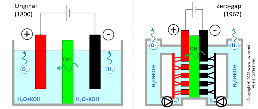
Comparison of original and zero-gap layouts for alkaline electrolysers
A newer design was proposed in 1967 by Costa and Grimes, using porous electrodes directly in contact with the separator, eliminating the gaps (hence the zero-gap name) and more than doubling achievable current density up 500 mA/cm2 . The installation becomes more compact for the same production rate of hydrogen and the reduced overpotentials limits electric consumption, i.e. improves efficiency. However, the zero-gap concept requires a double electrolyte circuit, pumps for fluid circulation and electrolyte/gas separators. The added auxiliary energy consumption cancels most of the above-mentioned efficiency gains, so that compactness, productivity and CAPEX are the main benefits.
Diaphragm material
The diaphragm separates reaction zones, is impermeable to gases but must be selectively permeable to ions. It is therefore a hydrophilic material that attracts water or other polar components, like OH-, but repels non-polar components like H2 or O2.
Historically, electrolyser diaphragms were made of 3mm-thick asbestos layers, leading to a total distance between electrodes of about 5mm . Because of asbestos degradation at high temperature, the operating temperature of such electrolysers was restricted to 80°C .
The ban on asbestos use forced manufacturers to switch to more elaborate materials. Today’s leading material for AEL diaphragm is a porous material sold under the trademarked name of Zirfon Perl and produced by Agfa. It is composed of an open mesh polyphenylene sulfide fabric, which is symmetrically coated with a mixture of ~15% polysulfone and ~85% of zirconium oxide (ZrO2). It has a thickness of 0.5 mm, a porosity of 55%, the same density as water and a maximum operating temperature of 110°C.
Some research efforts focus on developing new diaphragm material, notably sulphonated polyether-ether-ketones, capable of operating at higher temperature. Advanced alkaline electrolysers operating up to 150°C have already been demonstrated at the laboratory level.
Note that the structural component of the separator (polyphenylene sulfide for Zirfon Perl ) is alkali-resistant and can therefore also be used for the cell frame. As it generally has weak mechanical properties, it is reinforced with steel in pressurised electrolysers.
Electrode material
The electrodes are adjacent to the diaphragm and are made of corrosion-resistant metal. While solid electrodes of pure nickel were often used in the past, this is expensive and does not allow reaching maximum efficiency.
The oxygen-producing anode is either made of pure nickel, of a nickel coating on a steel core or of a nickel-iron alloy coated on a simple steel or nickel plate. Note that stainless steel has a lower overpotential than nickel (0.28V vs 0.61V) for the production of oxygen but a worst electric conductivity (1.45 MS/m vs 14.3 MS/m), so that choosing one or the other material implies a trade-off. Research about stainless steel electrodes or nickel-iron alloys with high iron content is on-going to offer a cheap alternative to nickel.
The hydrogen-producing cathode generally has a steel core with some catalytic coating . Depending on manufacturers and application type, the coating ranges from plain unactivated nickel to activated nickel alloys (NiMo, NiSn, NiS) or even platinum group metals. In contrast to the oxygen reaction, platinum group metals have very low overpotentials for the hydrogen reaction (0.09V for Pa and Pt or even 0.01V for platinized Pt), bettering both nickel (0.32V) and stainless steel (0.42V). Yet, a more cost-effective approach is to use some activated coatings where nickel is electroplated with some Mo, Sn or S (10-20%mass in the resulting alloy) to reduce the overpotential within the range of 0.11-0.27V. Nickel-sulphur is notably a very good catalyser, but the nickel-sulphur layer partly dissolves each time the electrolyser is stopped under the transient the increase of the electric potential. The hydrogen conversion efficiency therefore drops with time.
While conventional (gapped) electrolysers tend to use solid electrodes, zero-gap electrolysers use thin porous or perforated plates. For example, a thin 0.3mm pure nickel plate with 50% perforation can be used for the anode, while a similarly thin 0.3mm perforated nickel plate coated with NiS can be used for the cathode .
Atmospheric vs pressurised electrolysers
Most applications using hydrogen need pressurised hydrogen. Furthermore, hydrogen being a very light gas, it is never stored at ambient conditions. If not liquefied, it is stored compressed at 350 or 700 bar. Accordingly, producing hydrogen at atmospheric pressure requires further compression before storage.
To reduce if not fully eliminate the compression stage, hydrogen can also be produced with high-pressure electrolysers with demonstrator up to 170 bar. Nevertheless, pressure reduces bubble size which facilitates their transport through the diaphragm, increasing the cross-over losses. Pressure also facilitates the dissolution of impurity in the electrolyte (CO2 from air, for example). The overall consequence is a decrease in gas purity and in efficiency. Accordingly, most commercial electrolysers operate between 5 and 30 bar.
Efficiency and gas purity
The efficiency of an electrolyser is calculated as the ratio between the energy content of produced hydrogen and the electric energy consumed for electrolysis but also to run all the required auxiliary equipments (pumps, gas separator,…).
η = mH2 * LHVH2 / Eelec
Note that the appropriate energy content to consider is the lower heating value (LHV) of hydrogen, while some rare manufacturers still state efficiencies based on higher heating value (HHV) to display more advantageous numbers.
Industrial size alkaline electrolysers have an efficiency of 65+% (up to 67%) and produce hydrogen with a gas purity of 99.5+%vol (up to 99.9%vol). They generally operate between 60 and 90°C with a current density of 0.2 to 0.4 A/cm2, leading to a stack lifetime of 60.000 to 90.000 h . Note that an overhaul to replace the diaphragms and to reactivate the electrodes can be an alternative to replacing all the equipment lowering the environmental burden (see Life Cycle Analysis).
Beyond hydrogen, the electrolyser also produces oxygen with a purity up to 99.7 %vol without an auxiliary purification equipment. This oxygen can either be sold or vented to the atmosphere. Given the relatively low commercial value of oxygen compared to hydrogen, it is generally only sold if there is a local consumption or a pre-existing oxygen dispensing infrastructure.
Balance of energy and materials
Generating hydrogen by splitting water requires a significant amount of energy, about 142 MJ per kilogram of hydrogen for an ideal (100% efficient) electrolyser. With an efficiency of 66% for a realistic alkaline electrolyser, that number raises to 215 MJ per kg of H2 or 5.0 kWh per Nm3 of H2 (Nm3 = 1 m3 at normal conditions, 1 atm, 20°C). The large electric consumption explains why producing hydrogen from fossil fuel is today more affordable.
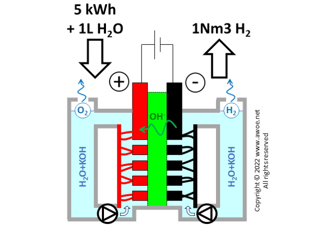
Balance of energy and materials in an alkaline electrolyser
Beyond electricity, producing hydrogen also consumes water within a ratio of about 1L of water per Nm3 of produced hydrogen. Note that part of this consumption occurs in the water purification process that precedes the actual electrolysis (water is first purified, then mix with the selected alkali). The significant water consumption is not an issue when operating an electrolyser based on wind power in Norway, but it is a huge roadblock when planning electrolyser farms in sun-rich arid environments.
Finally, the system consumes some alkali to maintain an appropriate concentration of OH- in the electrolyte. The order of magnitude is about 3.7 g of KOH per kg of H2 .
Industrial application
Large-scale alkaline water electrolysis is a mature industrial solution with numerous alkaline electrolyser suppliers operating for decades. An alkaline electrolyser is simply a stack of individual cells, so that it is an easily scalable technology.
There are 3 main electrolyser layouts:
- Oerlikon: square electrodes, operation at atmospheric pressure, no circulation pump
- Norsk Hydro: circular electrodes, operation at atmospheric pressure, with circulation pumps
- Zdansky/Lonza: circular electrodes, pressurised operation, with circulation pumps
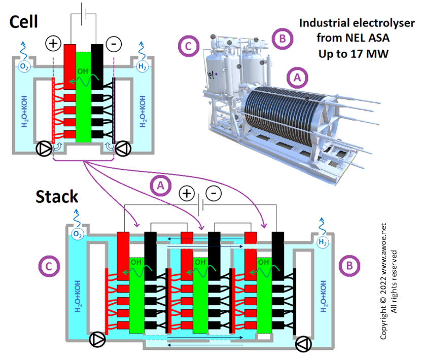
Schematics of an industrial alkaline electrolyser stack
Each individual alkaline cell operates with direct current (DC) at a voltage of 1.85 to 2.05V and has an efficiency of 70-80%. Numerous cells are combined in series within a stack creating a compact layout operated on a larger voltage.
Global efficiency of an industrial units lies between 60 and 67% because of the energy consumption of auxiliaries: AC/DC converter losses, water purifier, gas dryers on both O2 and H2 circuits, pumps circulating the electrolyte,...
An alkaline electrolyser can operate from nominal power down to ~15% of nominal, but efficiency drops below nominal conditions. The minimum operating load is defined by the minimum required current density. Below that threshold, the ion flow becomes weak and gas cross-over (H2 and O2 flowing through the separator due to molecular diffusion and solubility in the electrolyte) consumes a significant fraction of produced gases.
Alkaline electrolysers are essentially steady-state units. Large variations of current induce a sudden change in the amount of gas produced. Accumulation of gas bubbles can create some temporary electrical insulation, making the system inefficient or unstable. Sudden power variations must therefore be avoided, which does not make them suitable for direct coupling with highly fluctuating power sources, such as solar panels and wind turbines. Indirect coupling through an intermediate step storing and filtering the electric energy influx (a battery or a pumped hydro are valid options) is recommended.
Coupling with fluctuating power sources by activating/deactivating some sections of the electrolyser is not recommended either as start-up and shut-down procedures can produce large electrode potential variations that have a negative effect on the catalyser of each electrode, degrading their efficiency with time. The accumulation of start/stop cycles is the equivalent of oxidation/reduction cycles for the catalyst. This produces swelling and formation of catalyst oxides, which in turn produce mechanical stress and/or catalyst losses.
Anionic exchange membranes as a future for alkaline electrolysers
Anionic exchange membranes (AEM) are designed as a new alkaline approach that behaves similarly to Polymer Electrolysis Membranes (PEM) but with an OH- flow through the separator. The objective is to operate the electrolyser at higher pressure by using a non-porous media, i.e. not suffering from the cross-over losses experienced by alkaline electrolysers (AEL).
AEM does not need an electrolyte and only works with deionised water or a low concentration alkaline solution. The removal of the corrosive electrolyte limits the risks of leakage, improves volumetric stability, facilitates fluid handling and allows reducing the system size and weight.
AEM electrolysers use already existing non-porous membranes with high anionic conductivity. Yet, as of today, the anion conductivity in such membranes is significantly lower than cation conductivity in PEM membranes (OH- are less mobile than H+). These AEM membranes suffer from a lack of chemical stability at high pH, which is necessary for good anionic conductivity over a reasonable lifetime.
Nevertheless, some AEM units are already commercially available. They do not require any noble metal that can be replaced by low-cost transition metals (Fe, Ni, Co), just like AEL, while they can easily operate at higher pressure, just like PEM, removing the need for mechanical compression of hydrogen down the line.